Category

Test Equipment

Category

When running on a battery, it is important to know what parts of your circuit draw the most current. Profiling is a process where you look at sections of code or interactions with hardware to see how much power each requires. In this video, James shows four tools (and their tradeoffs) when profiling IoT or Edge Machine Learning devices. See if it makes more sense for you to use a Digital Multimeter (DMM), Power Supply with history graphs, an oscilloscope

Everywhere I look, I see a new device with a microcontroller, some sensors, a battery, and 2.4 GHz radio. All of these things connect to the Internet. It is like the internet is becoming full of these things. (There should be a catchy name for that.)

As a hardware designer, there is always a concern about how much power these devices consume. Modern microcontrollers (and sensors) are very dynamic devices. In other words, they go from sipping nanoamps to hundreds of milliamps in a few microseconds (or faster.) So, slower devices like a DMM may not be fastest enough to measure a device’s current consumption for an accurate view of its full behavior.

In this element14 Presents video, I compare Handheld DMM, Bench DMM, Power Supply (with graphing), Oscilloscope with Current probe, and Source Measurement Units (SMU) for measuring an IoT device’s current consumption. My favorite tool for this activity is the Nordic Power Profilier Kit 2. It is a USB-based SMU designed for measuring the power consumption of IoT devices. The best part is they only cost around $100!

When connecting multiple oscilloscope probes to a circuit, does each probe need to connect to ground?

The short answer is yes!

Why? The long answer is kind because of the ground loop. Remember, a circuit needs a closed path. And while on DC circuits we may rarely think about the distance of that path, it absolutely matters when there is an AC or frequency component.

When you do not connect each probe’s ground, the signal path because enormous since it must connect to the circuit’s ground through another probe. (See the animation in the video above.)

Every digital oscilloscope I have ever used has a menu or dialog for “acquisition modes.” And depending on the current settings, changing that acquisition mode does not seem to have an effect on the signal. Or sometimes, changing to something like Average mode can completely destroy your measurements.

It turns out, that the analog-to-digital converters in digital oscilloscopes can do more than just “sample” the data. Well, the ADCs just samples. The controller behind the ADC offers modes like Peak Detect and Average and High-Resolution.

In general, the key to these modes is looking at a signal that is relatively slow compared to your sample rate. For example, on my R&S RTM3004, it samples up to 5 gigasamples per second. However, if you are only looking at a 10 MHz clock with a rise time in the 10s of nanoseconds, you don’t need to sample that fast.

Or, more correctly, you do not need to STORE data that fast. An acquisition mode, like Peak Detect, reduces (or decimates) the information stored. For example, it might look at 4 samples and ONLY store the max and min values of those four. That way, you get half the effective sample rate, but your peak-to-peak voltage measurement will still be correct!

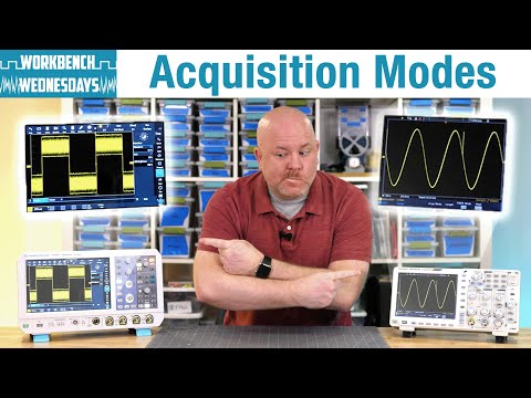
This Workbench Wednesdays video looks at various acquisition modes and addresses when to use Peak Detect, Averaging, and High-Resolution acquisition modes.

Bench power supplies are an essential piece of test equipment gear. And like most test gear, they have a wide range of capabilities. For example, the B&K Precision 9140 is a triple output supply that can output up to 300 watts. But, the basic capability isn’t what interested me about the supply. Instead, it was advanced features like rear panel triggers, adjustable slew rate, and built-in sequencing.

The element14 Community arranged for a B&K Precision 9140 power supply to be sent to me for a hands-on overview of those features.

When you cannot get an oscilloscope probe into a tight spot, can you just use a piece of wire? Sometimes. When signal integrity matters, you CAN use a low-cost DIY solder-in probe. These probes attenuate the signal and use an oscilloscope’s high-bandwidth 50-ohm input. James shows how to build some solder-in probes when they work and when they do not work in this video.

Special thanks to Shabaz on the element14 community for the guide used here.