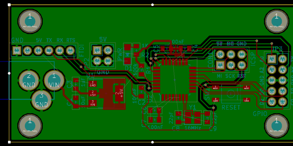
Continuing the DIY Arduino tutorial series, this AddOhms episode shows how to create a PCB in KiCad. I make a joke that the original design was a rectangle, which I found boring and pointless. So instead, I designed a triangle to give the board 3 points. Get it? Puns! I am calling it the Pryamiduino. To be honest, I found not having a constraint to be a problem. By forcing a specific board size and shape, many decisions were more manageable.
First design – Boring!
In the end, the video ended up more edited than I planned. KiCad is just so finicky and crashy that I could not make a coherent start to finish tutorial. At least, I could not work with a board at this level of complexity. Something simple like a 555 flasher would be easier to show from start to finish. I am planning some immediate follow-ups with quick tips on using KiCad. It is a frustrating suite of applications, but the results can be quite nice.
My recent SONOFF WiFi Switch experience reminded me of something from high school. I attended an off-site electronics class with my best friend. As teenage boys, we were prone to doing stupid things. One of our favorite games was to see who could handle the highest voltage. Our bench had a variable AC supply that went from 0 to 120 volts. So we would grab the alligator clips while the other person slowly turned the knob up. John once made it to 50 volts. I seem to recall my tolerance around 30 volts. First, DO NOT do this. It was stupid. Second, I think this game is why handling AC makes me so uncomfortable.
While I am not an electrician, I do know the basics about wiring mains AC circuits. So when one of my studio lights needed a new switch, I was okay to replace it. Mains AC does not scare me when it is off. I did not have a mechanical switch available. Instead, I opted for a SONOFF WiFi Switch. I did not intend to connect WiFi, at least not yet. I just wanted to control the light with the manual push button.
The clever solution seemed to be clever, at least for a few minutes. Suddenly the light turned off. I thought maybe there was a timeout for the manual button. Annoying, but workable. The lamp remained off for about another 2 minutes when I started to smell that unmistakeable burning plastic odor. Touching the case of the SONOFF identified the culprit immediately.
Great. So I have an AC mains switch that isn’t working, but I do not want to go poking my multimeter into it. What do I do?
Turns out, that SONOFF module was defective. I wanted to debug it, but I did not want to measure anything while connected to AC. Here’s how I used a thermal camera to debug my SONOFF.
What is a SONOFF?
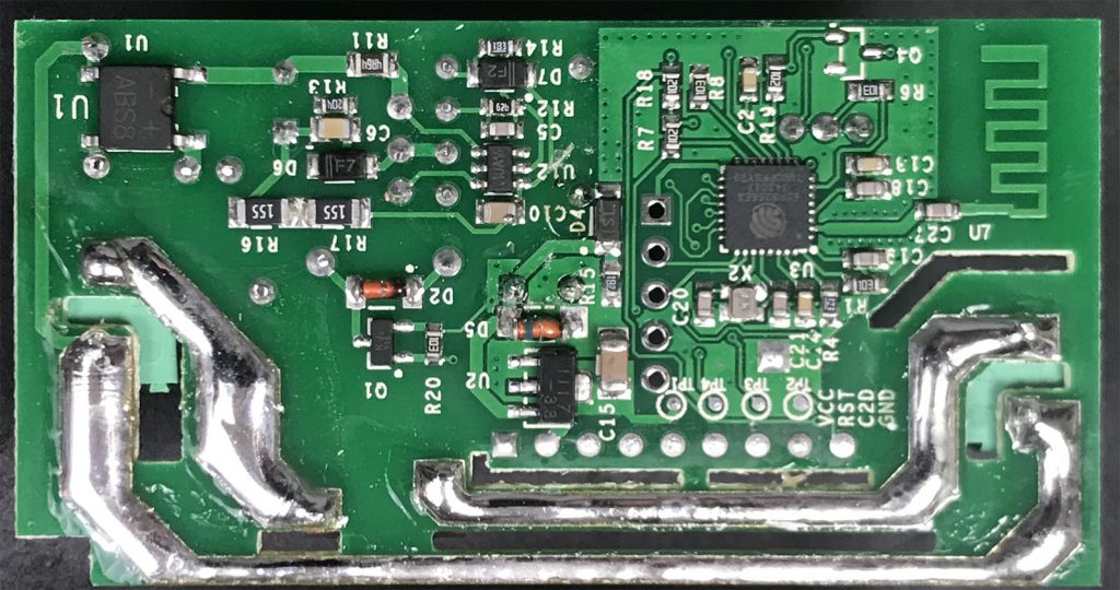
See the ESP8266 and Antenna?
The SONOFF WiFi switch is an inexpensive AC relay. Internally it has an ESP12 chip, which became popular with the ESP8266. There is even an unpopulatd serial header which can be used to reflash the firmware. Among hackers, these modules are a popular way to get an AC relay that is easily programmed.
Back in 2013, a Kickstarter ran for a project to put a python interpreter on a microcontroller. At the time I could not see the benefit. Cool project, but I asked myself: “why?” On my last Adafruit order, I received a free Circuit Playground Express. The board comes with CircuitPython pre-installed. After playing with Circuit Python, or CP, I finally “get it.”
For Valentine’s Day, I made an animated LED heart for a new love in my life, Circuit Python. Well, love is a bit of a strong word. The past couple of weeks I have been learning Circuit Python, and I am excited by what it offers.
What is Circuit Python?
It is a Python implementation that runs on microcontrollers. The code exists on the microcontroller as text. The interpreter runs the code from that text file. Circuit Python is built on, or based on, MicroPython. Adafruit is designing it to teach programming. It is easy to get started, just open up the code.py file from the auto-mounted drive and start typing. When you hit save, the code runs. That’s it.
While the buzzword “IoT “is relatively new, there has been a long time “internet of things” in operation. Those devices are called the far less sexy term “M2M” or machine-to-machine. These devices, around since the 90s, contain a microprocessor, some sensors, sometimes electromechanical hardware, and a cellular radio. These M2M devices were (and still are!) the early “Internet of Things.” Thanks to Hologram.io, you can join this new/old trend for free.
This post is not going to be a tidy tutorial. Instead, it is all the steps (and notes) I went through. I will cover:
Hardware pieces I am using
How to verify SIM808 (FONA) module is connected through Hologram via Serial Commands
How to send HTTP/POST requests (including SSL) with the SIM808 (FONA)
My (brute force) changes to the Adafruit FONA Library
Code for sending MQTT payload (GPS Coords) to a dafruit.io dashboard
When done, you will be able to build something like a battery powered GPS Tracker, that updates over cellular. If you are in a rush, grab all the code from the FONA GPS Tracker Github Project.
Signetics started as an IC manufacturer. In 1975 they were bought by Philips Semiconductors, which is now NXP. Interestingly the address in the datasheet, I think, was the original site. Today, it’s home to a Lowe’s Home Improvement Store. According to this Wikipedia article, it was created by John “Jack” Curtis. Apparently, it was included in a real Signetics catalog as a joke! Imagine that happening today. Additional information about the joke is available on sigwom.com. (Which may be written by Jack himself, not entirely sure.)
Like other websites, this one uses cookies to remember things. Mostly, I use Google Analytics to know how many people come here. ¯\_(ツ)_/¯
By clicking “Accept”, you consent to the use of ALL the cookies.
This website uses cookies to improve your experience while you navigate through the website. Out of these, the cookies that are categorized as necessary are stored on your browser as they are essential for the working of basic functionalities of the website. We also use third-party cookies that help us analyze and understand how you use this website. These cookies will be stored in your browser only with your consent. You also have the option to opt-out of these cookies. But opting out of some of these cookies may affect your browsing experience.
Necessary cookies are absolutely essential for the website to function properly. These cookies ensure basic functionalities and security features of the website, anonymously.
Cookie
Duration
Description
cookielawinfo-checkbox-advertisement
1 year
Set by the GDPR Cookie Consent plugin, this cookie is used to record the user consent for the cookies in the "Advertisement" category .
cookielawinfo-checkbox-analytics
11 months
This cookie is set by GDPR Cookie Consent plugin. The cookie is used to store the user consent for the cookies in the category "Analytics".
cookielawinfo-checkbox-functional
11 months
The cookie is set by GDPR cookie consent to record the user consent for the cookies in the category "Functional".
cookielawinfo-checkbox-necessary
11 months
This cookie is set by GDPR Cookie Consent plugin. The cookies is used to store the user consent for the cookies in the category "Necessary".
cookielawinfo-checkbox-others
11 months
This cookie is set by GDPR Cookie Consent plugin. The cookie is used to store the user consent for the cookies in the category "Other.
cookielawinfo-checkbox-performance
11 months
This cookie is set by GDPR Cookie Consent plugin. The cookie is used to store the user consent for the cookies in the category "Performance".
CookieLawInfoConsent
1 year
Records the default button state of the corresponding category & the status of CCPA. It works only in coordination with the primary cookie.
viewed_cookie_policy
11 months
The cookie is set by the GDPR Cookie Consent plugin and is used to store whether or not user has consented to the use of cookies. It does not store any personal data.
Functional cookies help to perform certain functionalities like sharing the content of the website on social media platforms, collect feedbacks, and other third-party features.
Cookie
Duration
Description
language
session
This cookie is used to store the language preference of the user.
Performance cookies are used to understand and analyze the key performance indexes of the website which helps in delivering a better user experience for the visitors.
Analytical cookies are used to understand how visitors interact with the website. These cookies help provide information on metrics the number of visitors, bounce rate, traffic source, etc.
Cookie
Duration
Description
_ga
2 years
The _ga cookie, installed by Google Analytics, calculates visitor, session and campaign data and also keeps track of site usage for the site's analytics report. The cookie stores information anonymously and assigns a randomly generated number to recognize unique visitors.
_ga_LHR6J24XSY
2 years
This cookie is installed by Google Analytics.
_gat_gtag_UA_42726312_1
1 minute
Set by Google to distinguish users.
_gid
1 day
Installed by Google Analytics, _gid cookie stores information on how visitors use a website, while also creating an analytics report of the website's performance. Some of the data that are collected include the number of visitors, their source, and the pages they visit anonymously.
browser_id
5 years
This cookie is used for identifying the visitor browser on re-visit to the website.
CONSENT
2 years
YouTube sets this cookie via embedded youtube-videos and registers anonymous statistical data.
Advertisement cookies are used to provide visitors with relevant ads and marketing campaigns. These cookies track visitors across websites and collect information to provide customized ads.
Cookie
Duration
Description
VISITOR_INFO1_LIVE
5 months 27 days
A cookie set by YouTube to measure bandwidth that determines whether the user gets the new or old player interface.
YSC
session
YSC cookie is set by Youtube and is used to track the views of embedded videos on Youtube pages.
yt-remote-connected-devices
never
YouTube sets this cookie to store the video preferences of the user using embedded YouTube video.
yt-remote-device-id
never
YouTube sets this cookie to store the video preferences of the user using embedded YouTube video.
yt.innertube::nextId
never
This cookie, set by YouTube, registers a unique ID to store data on what videos from YouTube the user has seen.
yt.innertube::requests
never
This cookie, set by YouTube, registers a unique ID to store data on what videos from YouTube the user has seen.


")