


Assembled control board. The processor is an ATmega328, RTC is DS1307 RTC, and LED driver is a TLC5904. There is also a FT232RL on the back side for USB to Serial connection, however, it doesn’t appear to be working.Next I’ll need to turn on the RTC and make sure it can actually keep time.


This is a quick video demonstrating the LED Matrix Shield for the Arduino. This Matrix is an 8×6 “Normal” matrix. (It is not Chairleplexed.) Blue LEDs were used to give it a brilliant hue and to provide another source of light in dimly lit apartment homes. Only one row of the Matrix is lit up at one time. This is done to save power and because the ATMega processor of the Arduino cannot source or sink more than 200mA of current.
Update 10/6/2012: Project page now available.
The scrolling message can be any string of characters between ASCII 32 and 255. The font is a 8×6 font based on 5×7 characters. Click below to see a picture of the Shield sitting on top of an Arduino.


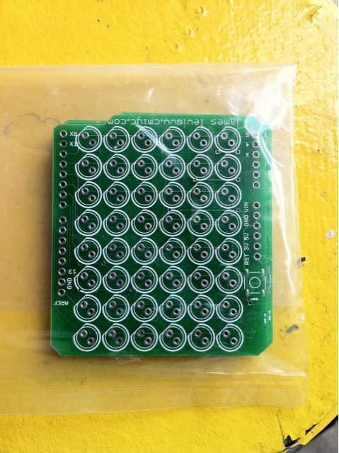
The PCB for my very first Arduino shield arrived today from BatchPCB. At first glance everything looks good. The silkscreen with my name and web address didn’t come out so well but that was probably my fault on trying to fit in too much.
Looking forward to assembling then with some Blue LEDs!

This screen shot is an all-layer view of my TLC5940 painter board. The 1st draft featured two TLC5940s, but I decided it made the board too large. Instead, I wanted the ability to mount the painter boards around the LED’s shadow box. This should make routing all the wires much easier.
This pattern is called Row Your Boat. As one of the strips starts to get brighter, a nearby strip will join in the fading. After completing a fade cycle, they start switching colors. There is a random strobe thrown in there as well. The first 10 seconds are with a diffuser (piece of paper), the last 10 seconds are without. The final panel will use a diffuser.
