Category

AddOhms

Category

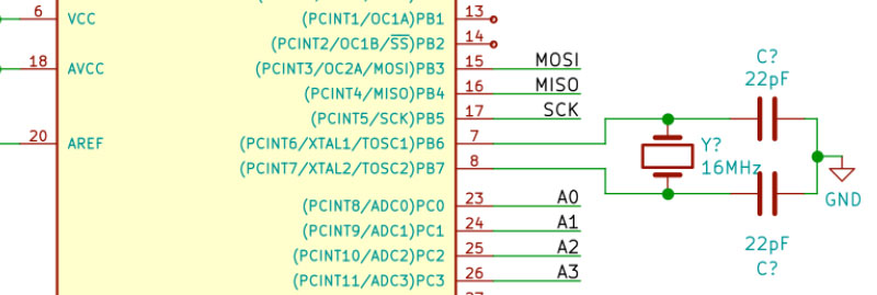
One of the last significant steps in a project is designing the custom PCB. This stage means creating a DIY Arduino board that is custom to the application. Two examples of my past projects are BinBoo, a Binary Clock, and Open Vapors, my reflow oven controller.

While working on a project for a friend, I got to thinking; it would be nice to have a checklist for circuit elements to include on a DIY Arduino board. In the early days, I forgot to add a filter cap to AREF, for example.

These tips are based on an 8-bit AVR design, like the ATmega328p chip. You could apply these tips to other 8-bit AVRs. Until now, I have not designed a custom board around a 32-Bit/ARM board. Though at only $16, I would be tempted to just solder the Teensy module directly to my finished board.

Below is a written list of items for a DIY Arduino checklist. If you’d like to see me design this board in KiCad, check out this AddOhms Tutorial.
The next AddOhms Tutorial is how to design a DIY Arduino board. What are the elements you need to include in your own circuit design? While editing the video, I ended up on this frame. It looked to me like I was praying. (At one point I was having serious technical issues with my equipment. But it is unrelated to that frame!) On Twitter, my friend Philip had a different take.

What caption comes to mind when you see this picture? Leave a comment with yours.

Op-Amp Question

If you can’t think of a caption, maybe you can help with a different question. What your favorite LM741 op amp alternative? I’ve been working on some tutorials and videos on op-amps. I’d like to incorporate something other than the old stand-by.

In April 2017 I backed a project on Kickstarter called “Crazy Circuits.” It looked like a cool concept that was well developed, so I even included it in the Baldengineer Newsletter. I do not typically promote Kickstarter projects–unless they are exceptional in some way. I liked the concept of circuits that worked with existing LEGO-sized boards and pieces. Their shipping was a couple of months off, but nothing compared to some Kickstarter disasters. I received my Crazy Circuits kit in November, compared to the promised September.

The product concept is simple enough I could not put the time into a full write-up or an AddOhms Tutorial video. So, instead, I featured it on an AddOhms Live stream. For example, to connect an LED to a battery, just snap in some conductive “tape.” In the video, I am building my first two circuits ever. I do think the ribbon takes a bit of practice. However, as I said earlier, I like that it adapts to existing LEGO bricks rather well.

If you know someone interested in electronics but afraid of soldering, I think the Crazy Circuits kits are an interesting option. The case they come in is nice. (I know, strange thing to throw out there, but I do like the sorting case.)

After the hands-on, which lasts about 30 minutes, I answer viewer questions. These questions cover op-amps, LEDs, and capacitors.

Watch Crazy Circuits Hands-On, on YouTube

Can you use voltage dividers as regulators? What if you add a Zener Diode? In this AddOhms episode, I show what happens when you try to power a complex circuit like an ESP8266 with a voltage divider instead of a regulator. (Spoiler: Get a voltage regulator.) This video tutorial is related to a write up I did recently on Zener Diodes. For questions or comments visit the AddOhms Discussion Forum.

Behind the scenes

A significant change for this AddOhms Episode is that I moved from Final Cut Pro X to Premiere Pro. I also shot the entire video in 4K, even though the output is 1080p. Animations were still done as 1080p compositions. One snag I ran into, the color corrections I applied in PPro, didn’t seem to get exported. You might notice when the breadboard is on screen, it has a very slight yellow tint to it.

I’ve been changing how I produce the videos. It’s shortening the cycle time. The key is that I’m not trying to animate every scene. The amount of work involved is just too much. I animate practically every frame. So in a 6-minute video, that’s just too much.

By the way, there are two easter eggs in this episode. Can you find them?

Voltage Dividers as Regulators on YouTube

The first part of the tutorial looks inside of a Brushless DC Motor, or, BLDC. Then I show a discrete transistor circuit that can drive one. Of course, you’ll need a Microcontroller like an Arduino to drive it! Lastly, I briefly talk about an ESC.

Overall, a BLDC is better than a Brushed DC Motor (talked about those on #20) because:

  1. There are no brushes to wear out
  2. No sparks when the motor spins
  3. You can get way faster RPMs out of a BLDC.

Check out the AddOhms #21: Brushless DC (BLDC) Motors. Show notes are available here.