Author

James Lewis

Browsing

In the past, I’ve covered how to reset Arduino millis() and have provided a growing list of examples using millis(). While reviewing the code for the elegoo Penguin Bot, I was reminded of a millis() mistake I see often: addition. The only way to properly handle millis() rollover is with subtraction. Let’s look at why (and how.)

What is Arduino millis()

The Arduino library has a function called millis() which returns the number of milliseconds the processor has been running. On other platforms, you might see references to a “tick counter.” It is the same idea. A hardware timer keeps incrementing a counter at a known rate. In this case, that rate is milliseconds.

A mistake new programmers often make is trying to “reset millis().” A better method is to compare two time-stamps based on millis(). So this if-statement is comparing a previous timestamp to the current value of millis().

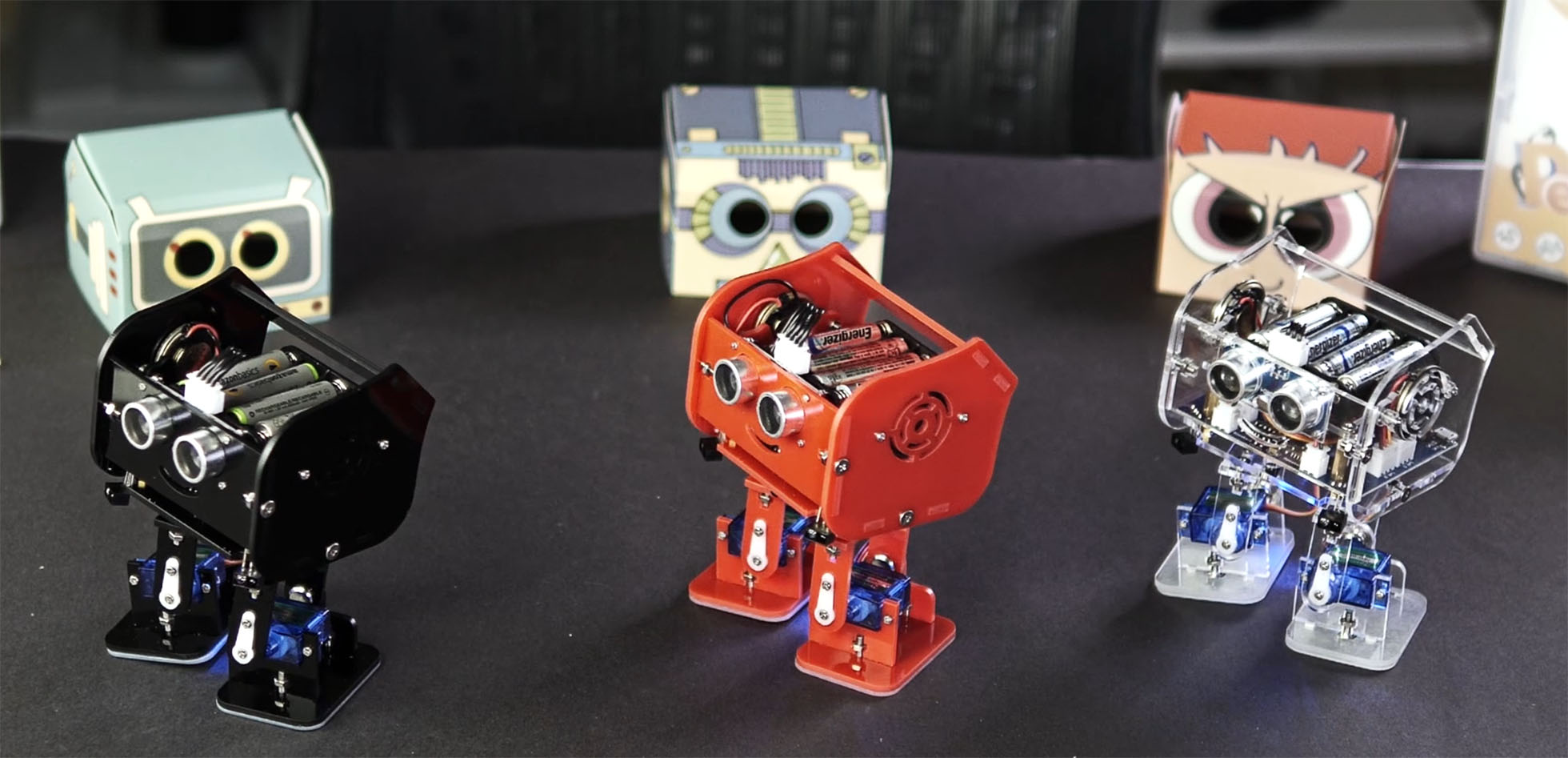
Recently I received three packages from Elegoo Industries. They are a company based in Shenzhen China. Before those packages, I noticed their name several times on various electronics kits on Amazon. They asked me if I’d help them with a video that shows how to assemble their latest creation: Penguin Bot.

There is not much point in sharing that video with you unless you’ve purchased one. So instead, here is my review, or hands-on, of the kit. I will, however, show you a short Instagram video I made to show off Penguin Bot’s cuteness.

Learning to use a new oscilloscope can be daunting. In this video, I show 5 measurements you can make using just an Arduino as your DUT. Learn how to offset voltage, setup measurements, enable infinite persistence, save reference waveforms, AND trigger (and decode) serial signals. For this video, Rohde & Schwarz was kind enough to send me an RTM3004. This video is a follow-up from an ealier blog post which featured 6 scope measurements you can make with an Arduino.

Check out the AddOhms Episode 28 Show Notes for links related to the episode.

Watch On YouTube

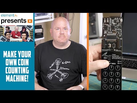
Making tutorial videos and project videos is a very different process. It is very easy to script a tutorial. In fact, I think it is a necessary step. Project videos, on the other hand, are more organic. In this project, I build a capacitive activated coin bank, based on this Coin Acceptor from Adafruit. It uses an MSP430 to do capacitive sensing and then a Pryamiduino to control the rest of the electronics. In the end, I do some classic AddOhms special effects to demonstrate how the project works. For detailed notes and design files, hit the button below for the element14 project page.

Bank to the Future on e14

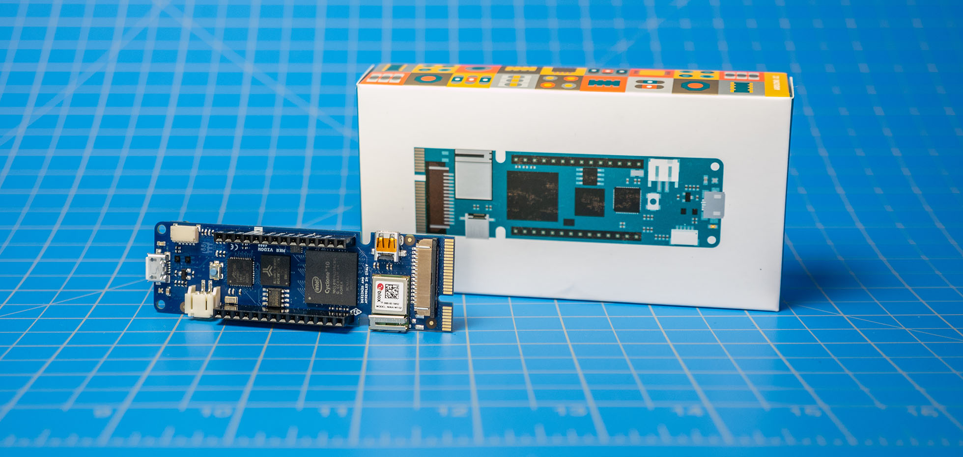
Earlier this week, I looked at the Arduino MKR Vidor 4000 during an AddOhms live stream. My goal was to understand the Vidor better. It is the new FPGA-based Arduino which started shipping this month. It runs about $60. You can learn more at the Vidor Product Page on the Arduino website.

In this post, I briefly touch on the difference between an FPGA and a microcontroller. Then I walk you around the MKR Vidor 4000’s board. Using one of the examples, I talk a bit about how the various chips communicate with each other. This section also highlights what makes the Arduino FPGA board different from other development boards. Lastly, I answer “should you buy an Arduino MKR Vidor 4000?”