Recently I picked up a device called Logic from Saleae. It’s a 4-channel USB-based logic analyzer. While learning how the simple, but effective, UI works I ran some timing benchmarks on my Arduino Uno. The subject? digitalWrite(). I wanted to know how fastdigitalWrite() could turn on two (or more) pins.
Almost all Arduino users start out with the simple “blink” sketch. Turn pin 13 ON, delay, turn it OFF, and delay again. The heart of this version of “Hello World!” is the digitalWrite() function. Many Arduino users never even think about all of the stuff this single function call hides.
In this post, let’s compare the speed of digitalWrite() to direct port manipulation, using a logic analyzer.
digitalWrite()
Using this simple program, I tried toggling Pin 8 and Pin 9, one call after another. For most Arduino users, this is the fastest way they know to change two pins. Some may even think this happens “at the same time”, or close enough. Does it?
const int waitTime = 5;

void setup() {
  // enable pin output
  pinMode(8,OUTPUT);
  pinMode(9,OUTPUT);

  // give the pins an initial value
  digitalWrite(8,LOW);
  digitalWrite(9,LOW);
}

void loop() {
   // turn the pins on
   digitalWrite(8,HIGH);
   digitalWrite(9,HIGH);
   delay(waitTime);

   // turn the pins off
   digitalWrite(8,LOW);
   digitalWrite(9,LOW);
   delay(waitTime);
}
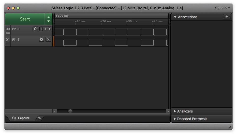
The delay(waitTime) is so that we can clearly see the transitions on our Logic Analyzer’s waveform screen. Figure 1 shows the capture from the Logic.
Figure 1 – digitalWrite() capture
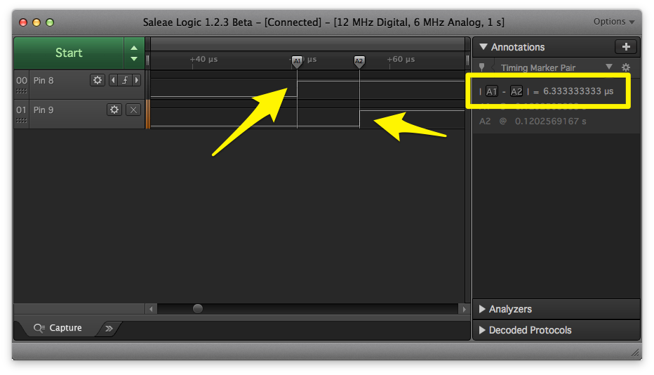
Looks like everything is perfectly in sync doesn’t it? When we zoom in and turn on markers, we see a different story, shown in Figure 2. Same data as Figure 1, but the scale has changed.
Figure 2 – Zoom-In on digitalWrite() capture
The difference between marker A1 and A2 shows Pin 9 turns on about 6us after Pin 8. At 16MHz, that’s nearly 100 clock cycles from one pin to the next. Fast for us humans, but rather slow for microcontrollers.
For most projects, this time between pin transitions is fine. However, what if you need those transitions to happen closer together? Well, one option would be to use the registers of the AVR chip and toggle them directly, instead of digitalWrite().
PORTx
Behind the scenes, digitalWrite() is doing a bunch of things for you. It’s mapping the Pin Number you give it, to a physical pin on an Arduino board. Next it figures out the state of the pin, to make sure it knows what to do next. Then it adjusts the appropriate “register” for you. (A register is a series of transistors that keep track of very simple information, like if an I/O pin is input or output.) All of these things take time.
So let’s look what happens when we skip the hand-holding of digitalWrite(). Here’s how we go directly to the hardware’s registers ourselves.
const int waitTime = 5;

void setup() {
  // enable pin output
  pinMode(8,OUTPUT);
  pinMode(9,OUTPUT);

  // give the pins an initial value
  digitalWrite(8,LOW);
  digitalWrite(9,LOW);
}

void loop() {
   // turn on pin 8
   PORTB = PORTB | B00000001;
   // turn on pin 9
   PORTB = PORTB | B00000010;
   delay(waitTime);

   // turn off pin 8
   PORTB = PORTB & B11111110;
   PORTB = PORTB & B11111101;
   delay(waitTime);
}
Using the code, we change the state of pins 8 (PB0) and 9 (PB1). Note, this code only works on ATmega328-based boards like the Uno and Nano.
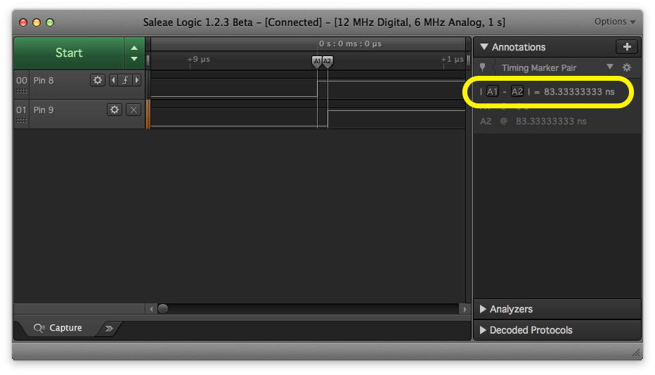
Figure 3 – Two PORTB Calls
Ah-ha! Now our time between pins is down to just 83ns. Or… is it? This logic analyzer samples at 12MHz. Convert that to time between samples with 1 / 12MHz, and you get 83ns. Since our sample period is 83ns, and our measurement is 83ns, the data is suspect. We can’t accurately measure the time between pins with this logic analyzer! However, we do know the transistion occured within 1 sample period of the analyzer’s capture. That means register manipulation is at least 60 times faster than using digitalWrite().
But wait, there’s more!
A Single PORTx Call
This magic line of code turns on Pin 8.
PORTB = PORTB | B00000001;
The “|” character is a C-operator called “Bitwise-OR.” Bitwise functions perform an individual binary-OR on each bit of PORTB and the binary number.
To turn a bit ON, we Bitwise-OR that bit with 1 and all the other bits 0. To turn a bit OFF, we BitWise-AND that bit with 0 and all the other bits 1. Why? That’ll need another post.
On the ATmega328, PORTB controls pins 8-13. Why don’t we turn on bits 0 (Pin 8) and 1 (Pin 9) at the same time with a single line of code?
const int waitTime = 5;

void setup() {
  // enable pin output
  pinMode(8,OUTPUT);
  pinMode(9,OUTPUT);

  // give the pins an initial value
  digitalWrite(8,LOW);
  digitalWrite(9,LOW);
}

void loop() {
   // turn on pin 8 and 9, at the same time
   PORTB = PORTB | B00000011;
   delay(waitTime);

   // turn off pin 8 and 9, at the same time
   PORTB = PORTB & B11111100;
   delay(waitTime);
}
Now the code is simplified to this example.
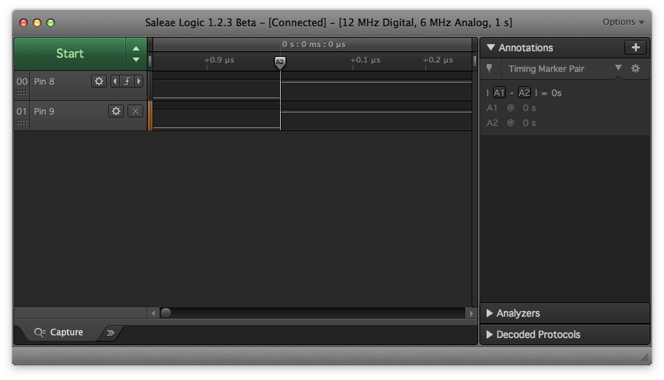
Figure 4 – 0s with a single PORTB call
And now! The logic analyzer sees both bits changing at the SAME time.
Conclusion
When you switch to using direct port manipulation of an Arduino, you start to limit what boards the code will work on. Each ATmega chip has different PORTs that map to the Arduino board’s pins. One of the benefits of digitalWrite() is that it figures that mapping out for you. One of the downsides is that it takes, in microcontroller terms, much longer to operate than direct port manipulation.
I highly recommend the Logic from Saleae. For only about $110 it has decent specs, good hardware build, and simple to use software, it’s great for watching up to 4 pins of an Arduino project. You can buy the Logic from Jameco here.
Fan of making things beep, blink and fly. Created AddOhms. Stream on Twitch. Video Host on element14 Presents and writing for Hackster.IO. Call sign KN6FGY.
Thank you for the nice articles that you write!
As a newbie in electronics, it’s hard to find good information to aid learning for a couple of topics.
Oscilliscopes and logic analyzers are such a topic.
Most cover the usage and software but there is hardly focus on how to connect these devices, the do’s & don’t and some background knowledge to learn and understand more.
Thanks for a very interesting and informative article on port calls vs. digitalWrite. This tutorial gives an alternate & more in-depth understanding of subject matter not usually covered in typical tutorials.
Like other websites, this one uses cookies to remember things. Mostly, I use Google Analytics to know how many people come here. ¯\_(ツ)_/¯
By clicking “Accept”, you consent to the use of ALL the cookies.
This website uses cookies to improve your experience while you navigate through the website. Out of these, the cookies that are categorized as necessary are stored on your browser as they are essential for the working of basic functionalities of the website. We also use third-party cookies that help us analyze and understand how you use this website. These cookies will be stored in your browser only with your consent. You also have the option to opt-out of these cookies. But opting out of some of these cookies may affect your browsing experience.
Necessary cookies are absolutely essential for the website to function properly. These cookies ensure basic functionalities and security features of the website, anonymously.
Cookie
Duration
Description
cookielawinfo-checkbox-advertisement
1 year
Set by the GDPR Cookie Consent plugin, this cookie is used to record the user consent for the cookies in the "Advertisement" category .
cookielawinfo-checkbox-analytics
11 months
This cookie is set by GDPR Cookie Consent plugin. The cookie is used to store the user consent for the cookies in the category "Analytics".
cookielawinfo-checkbox-functional
11 months
The cookie is set by GDPR cookie consent to record the user consent for the cookies in the category "Functional".
cookielawinfo-checkbox-necessary
11 months
This cookie is set by GDPR Cookie Consent plugin. The cookies is used to store the user consent for the cookies in the category "Necessary".
cookielawinfo-checkbox-others
11 months
This cookie is set by GDPR Cookie Consent plugin. The cookie is used to store the user consent for the cookies in the category "Other.
cookielawinfo-checkbox-performance
11 months
This cookie is set by GDPR Cookie Consent plugin. The cookie is used to store the user consent for the cookies in the category "Performance".
CookieLawInfoConsent
1 year
Records the default button state of the corresponding category & the status of CCPA. It works only in coordination with the primary cookie.
viewed_cookie_policy
11 months
The cookie is set by the GDPR Cookie Consent plugin and is used to store whether or not user has consented to the use of cookies. It does not store any personal data.
Functional cookies help to perform certain functionalities like sharing the content of the website on social media platforms, collect feedbacks, and other third-party features.
Cookie
Duration
Description
language
session
This cookie is used to store the language preference of the user.
Performance cookies are used to understand and analyze the key performance indexes of the website which helps in delivering a better user experience for the visitors.
Analytical cookies are used to understand how visitors interact with the website. These cookies help provide information on metrics the number of visitors, bounce rate, traffic source, etc.
Cookie
Duration
Description
_ga
2 years
The _ga cookie, installed by Google Analytics, calculates visitor, session and campaign data and also keeps track of site usage for the site's analytics report. The cookie stores information anonymously and assigns a randomly generated number to recognize unique visitors.
_ga_LHR6J24XSY
2 years
This cookie is installed by Google Analytics.
_gat_gtag_UA_42726312_1
1 minute
Set by Google to distinguish users.
_gid
1 day
Installed by Google Analytics, _gid cookie stores information on how visitors use a website, while also creating an analytics report of the website's performance. Some of the data that are collected include the number of visitors, their source, and the pages they visit anonymously.
browser_id
5 years
This cookie is used for identifying the visitor browser on re-visit to the website.
CONSENT
2 years
YouTube sets this cookie via embedded youtube-videos and registers anonymous statistical data.
Advertisement cookies are used to provide visitors with relevant ads and marketing campaigns. These cookies track visitors across websites and collect information to provide customized ads.
Cookie
Duration
Description
VISITOR_INFO1_LIVE
5 months 27 days
A cookie set by YouTube to measure bandwidth that determines whether the user gets the new or old player interface.
YSC
session
YSC cookie is set by Youtube and is used to track the views of embedded videos on Youtube pages.
yt-remote-connected-devices
never
YouTube sets this cookie to store the video preferences of the user using embedded YouTube video.
yt-remote-device-id
never
YouTube sets this cookie to store the video preferences of the user using embedded YouTube video.
yt.innertube::nextId
never
This cookie, set by YouTube, registers a unique ID to store data on what videos from YouTube the user has seen.
yt.innertube::requests
never
This cookie, set by YouTube, registers a unique ID to store data on what videos from YouTube the user has seen.
 with a Logic Analyzer")


3 Comments
How about a PINB = B00000011 ?
Writing a one to the port’s *INPUT* register does a toggle for those bits without the read-modify-write cycle.
PINB = B00000011;PINB = B00000011; // toggles two pins twice near the limits of my test equipment
Thank you for the nice articles that you write!
As a newbie in electronics, it’s hard to find good information to aid learning for a couple of topics.
Oscilliscopes and logic analyzers are such a topic.
Most cover the usage and software but there is hardly focus on how to connect these devices, the do’s & don’t and some background knowledge to learn and understand more.
Thanks for a very interesting and informative article on port calls vs. digitalWrite. This tutorial gives an alternate & more in-depth understanding of subject matter not usually covered in typical tutorials.