Category

Schematics

Category

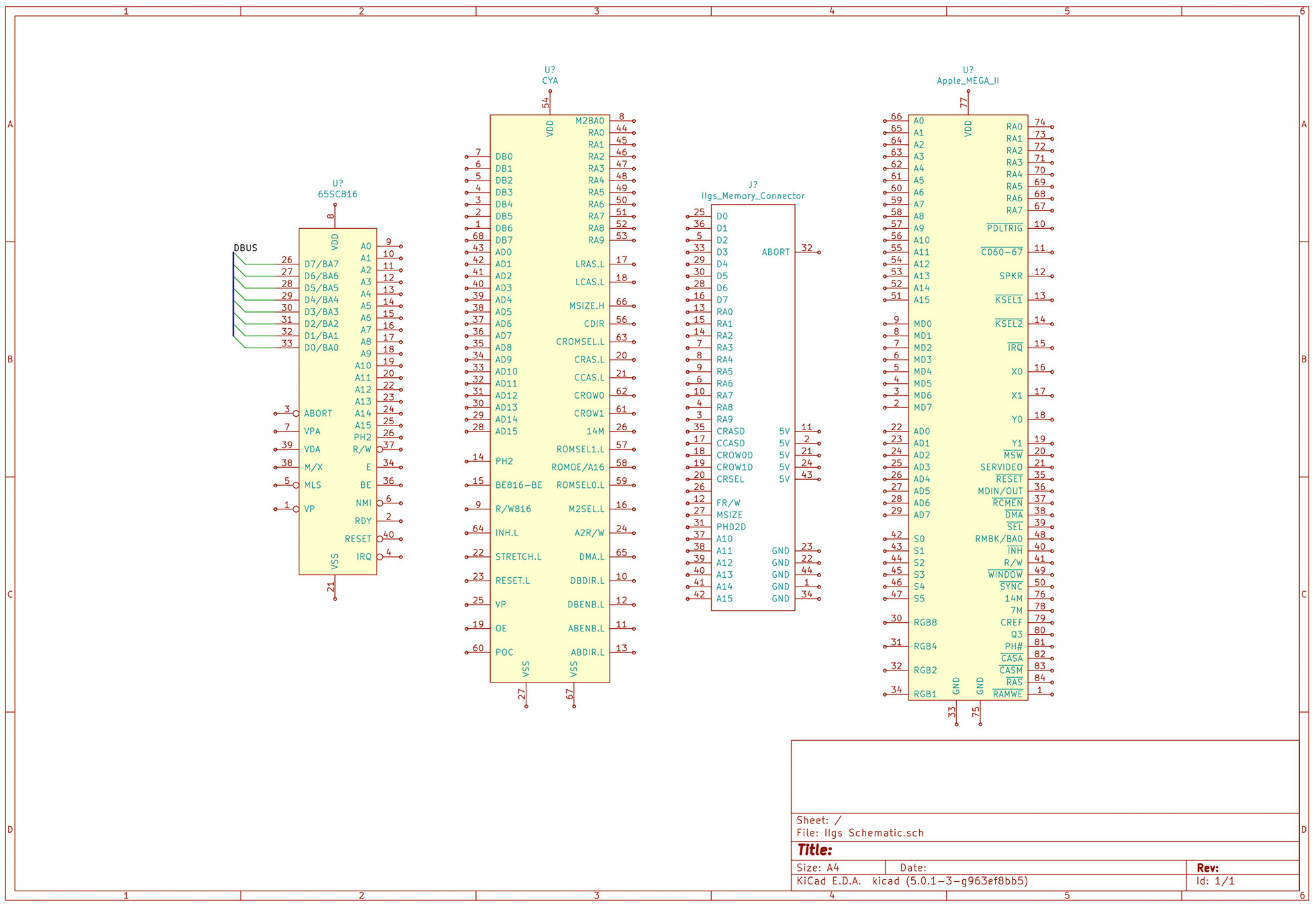
A new project I have started working on involves the Apple IIgs. It was Apple’s last 16-bit (and 8-bit) computer. Inside are many application specific integrated circuits, or ASICs, that make the IIgs an extraordinary member of the Apple II family. One chip, in particular, is called the “MEGA-II.” This chip takes all of the individual logic chips from the original Apple II design and incorporates them into a single 84-pin PLCC.

The project I have in mind needs the MEGA-II. I need to design some printed circuit boards for it and a few other IIgs chips. That goal means I need at least one custom Kicad schematic symbol. I plan to create a custom library of Apple IIgs components.

Like other computers from the same era, complete schematics are available. However, they are not in a modern format. Since I need to create symbols for so many of the chips as it is, I may end up re-creating the entire IIgs schematic.

For now, here is the process I use to create custom KiCad schematic symbols and parts.

One of the last significant steps in a project is designing the custom PCB. This stage means creating a DIY Arduino board that is custom to the application. Two examples of my past projects are BinBoo, a Binary Clock, and Open Vapors, my reflow oven controller.

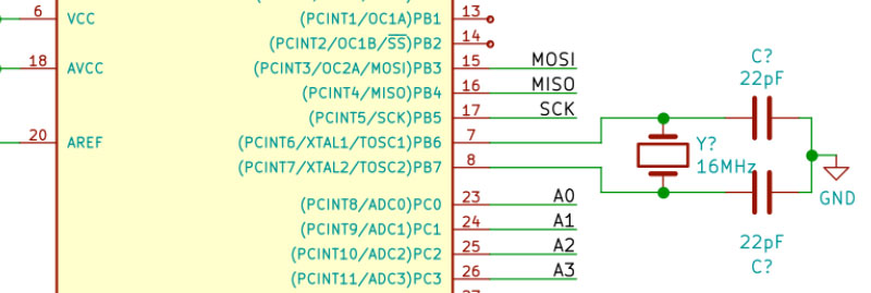
While working on a project for a friend, I got to thinking; it would be nice to have a checklist for circuit elements to include on a DIY Arduino board. In the early days, I forgot to add a filter cap to AREF, for example.

These tips are based on an 8-bit AVR design, like the ATmega328p chip. You could apply these tips to other 8-bit AVRs. Until now, I have not designed a custom board around a 32-Bit/ARM board. Though at only $16, I would be tempted to just solder the Teensy module directly to my finished board.

Below is a written list of items for a DIY Arduino checklist. If you’d like to see me design this board in KiCad, check out this AddOhms Tutorial.

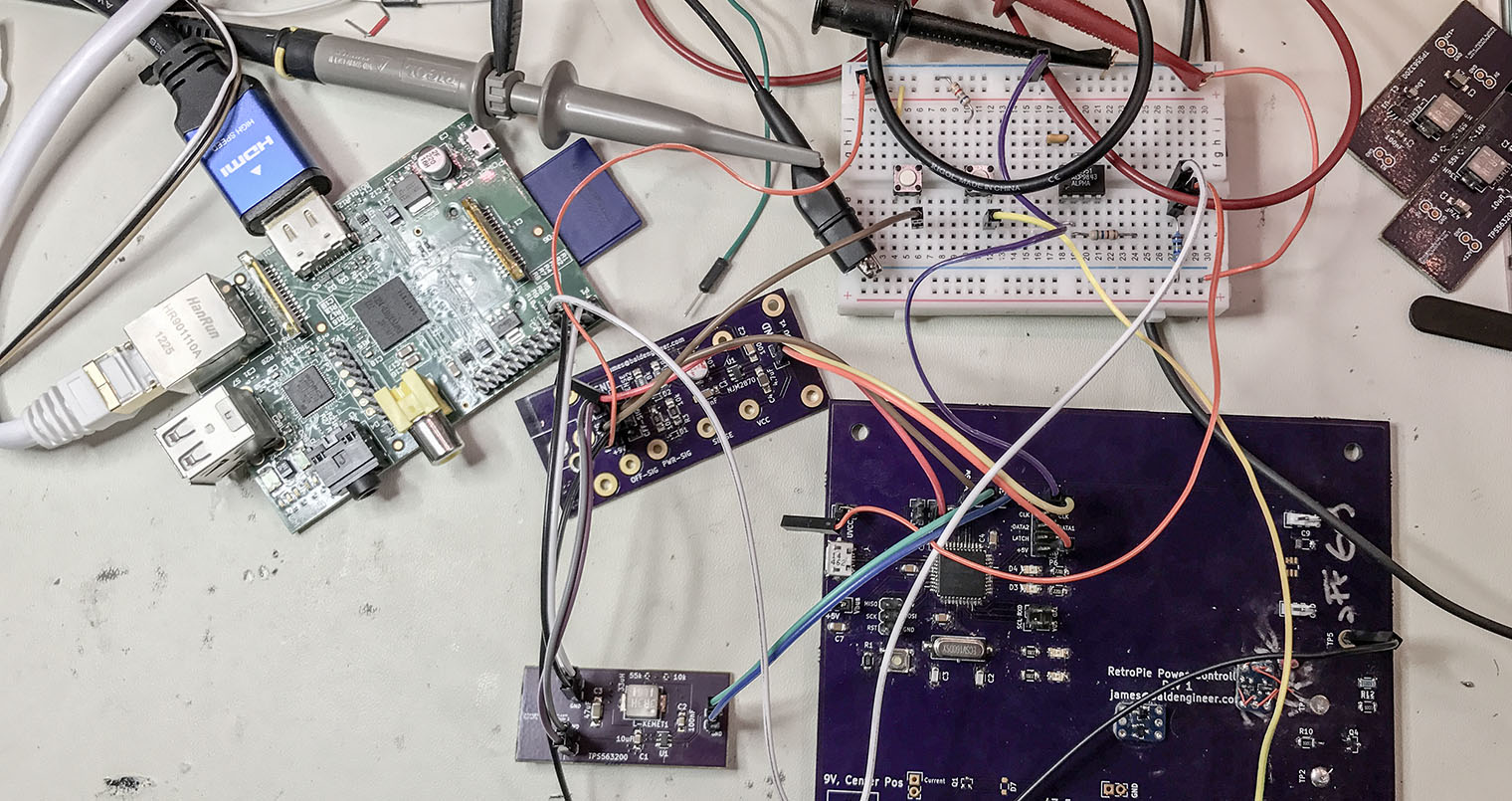
The RetroPie project enables retro-gaming with a Raspberry Pi. All of the Pi models have enough computing power to emulate the major 8-bit and 16-bit computers of the 80s and 90s. With the Pi 3 I have even been able to play PS1 games with no problem. My current project is to put my Raspberry Pi running RetroPie into an old Super Famicom (SFC), or SNES, case. The catch? I want the original SPST power switch to work. And by work, I mean allow the Raspberry Pi to shutdown properly when the switch goes into the off position.  To accomplish this task, I am building a Raspberry Pi soft power controller.

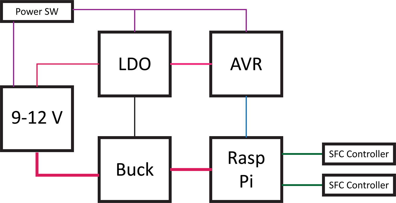
Raspberry Pi Soft Power Block Diagram

Here’s a block diagram of the power controller. The basic blocks in a Raspberry Pi soft power controller include the LDO, a switching supply for the Pi, an AVR-based microcontroller, and the Raspberry Pi. This post will describe each of these hardware blocks.

One design objective was to draw as little current as possible when off. For my RetroPie, I will not be running on battery. However, I do not like the idea of wasting energy when something is turned “OFF.”

This overview is a multi-post write-up. This first part is on the hardware. In the next post, I will explain the AVR’s firmware. Later, I will come back to the Raspberry Pi side of the project.

Last week’s post was on Project Sharing Sites. I’m using two for this project. Hackster.io will host the build log while GitHub has all of the design files. And by all of the file I mean the schematics, firmware, laser cutter files (soon), and Raspberry Pi code.


A KiCad BOM is a list of all the parts your design is using. The term BOM, or bill-of-materials, is standard for supply chain management and does not just apply to electronics. KiCad’s eeschema has a BOM export feature. Unfortunately as of Version 4.0, this feature is still somewhat lacking. Given the limitations, here are some tips to take your KiCad BOM from Schematic to Mouser.

Spending a few extra minutes while capturing (drawing) your schematic thinking about your KiCad BOM can save you a ton of time later on. Moreover, as you build up a database of parts, these extra minutes turn into seconds. Here are a couple of ways to describe your parts, especially passive components, better while drawing schematics in KiCad.

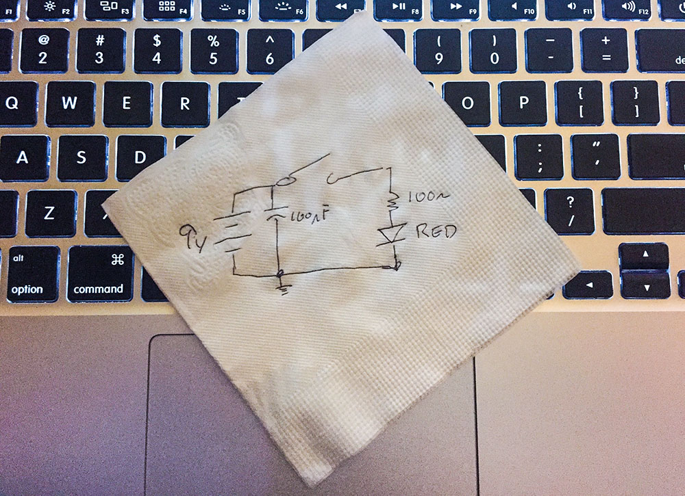
Engineers make a schematic to explain their circuits.

One time I was looking for a non-tourist pub in Japan. I asked someone for help. She said, “I’m sorry, but I do not speak good English. I will bring my friend, and she will draw you a map.” (Exact quote!) The map her friend drew, gave directions to a bar with a “Neon Yellow Sing.” She meant “sign.”

The map was the method we used to communicate with each other, even though we didn’t both speak English. With this crude but useful map, I could find my next drinking place destination.

Schematics are the same as this map. Even if you don’t speak the same language, you can communicate how a circuit works when you make a schematic.

Use one of these five tools, when you need to a document a circuit or when you need to ask for help.