
Dreaming of bringing a new hardware product to market? Perhaps you think your product will make the world a better place, or maybe you just dream of making millions of dollars.
Developing a prototype based on an Arduino (Genuino outside the USA), or other development kit, is a great first step. But there is still much work to do if you want to make your product into something that can be manufactured in volume and sold to the masses.
So I’m going to break down the process for you into a few manageable steps:
Step #1 – Design the Microcontroller Circuit
The Arduino is a microcontroller development kit, so the first step is designing a custom microcontroller schematic to replace the Arduino. And the first step of designing a microcontroller schematic, is to select the microcontroller.
The easiest strategy is to select the same microcontroller as is used in your Arduino model. For example, the Arduino Uno uses the Atmel Atmega328P. In fact, all Arduino models are based on Atmel microcontrollers, except for the 101 which is based on an Intel chip.
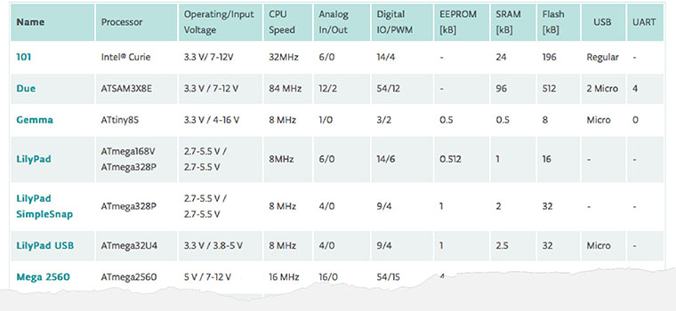
There are definitely microcontrollers available that are more powerful than the ATmega. There are plenty of cheaper ones available as well, such as a basic Cortex ARM microcontroller. But sticking with the same microcontroller as used by your development kit prototype will make the transition much easier. This is true for both hardware design and software development.
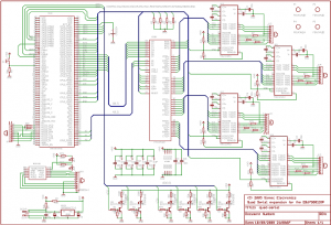
One of the beauties of Arduino is that it’s an open-source platform so you can pretty much copy the schematic as much as needed. Let’s take a look at the schematic for the Uno.
You’ll notice from the schematic above that the Uno consists of two primary chips: U3 and U4. But wait a minute, why are both of these chips microcontrollers? U4 is an ATmega328P which is the primary microcontroller. The sole purpose of U3 (ATmega16U2) is to serve as a USB to serial converter since most lower cost microcontrollers don’t include built-in USB support. Other Arduinos use a specialized USB-to-serial chip from FTDI.
So if your product doesn’t require USB data communication (USB power/charging is different), then you can just eliminate U3 which greatly simplifies the design.
As is true with most microcontroller designs, the ATmega328P circuit consists of power, a crystal oscillator, a programming interface, multiple serial interfaces, and lots of I/O.
The power section of the Uno uses an NCP1117 linear regulator to generate a 5V rail from the 6-20V input supply that can source up to 1A of current. Another linear regulator (LP2985) is used to generate a 3.3V reference voltage. The 3.3V reference is fed into a comparator (U5A) that is used to switch to USB power, if available, when no power supply is plugged in.
Step #2 – Design the Schematic Circuits for Any Shields
 Now that you have your core microcontroller schematic circuit designed the next step is to design the circuits for any Arduino shields you may be using.
Just like with the microcontroller schematic, the easiest strategy for designing a custom circuit to replace a shield is to start with the schematic for the shield. The beauty of an open-source hardware platform like Arduino is that you can easily access the full circuit schematic.
Most shields are going to communicate with the microcontroller via one of the following serial interfaces: UART, I2C, or SPI. In most cases a few GPIO lines will also be required for interfacing to a shield. All microcontrollers offer a UART interface. Most, but not all, microcontrollers also offer I2C and SPI interfaces. Just be sure your microcontroller includes whatever serial interface is required to work with your shield circuit.
Be warned that many shields are actually more complex to design than the core microcontroller circuit. This is especially true for wireless functions such as Bluetooth, WiFi, GSM, and GPS. Although for wireless functions it’s usually the PCB layout design (see step #3 below) that is so critical, and the schematic isn’t necessarily all that complicated.
Step #3 – Design the Printed Circuit Board (PCB)
Once you have the full schematic circuit designed for your product, the next step is to turn it into a real world Printed Circuit Board (PCB).
Although you’ll also be able to access the PCB layout file for the Arduino and any shields, you will most likely need to completely redesign the PCB. That is unless you don’t care about the physical size of your PCB. Regardless, having a PCB layout to use as a reference will be a great help.
If your product offers any wireless functionality then you’ll need to pay special attention to the PCB layout for the antenna. Laying out an RF antenna is not only critical, but rather complex. In fact, most electrical engineers are clueless when it comes to proper antenna layout. Incorrect antenna layout is one of the most common mistakes on PCB layouts.
For maximum power transfer with the antenna it’s absolutely essential that the antenna is properly matched. In most cases, this means making the antenna feed (called a microstrip) a 50 ohm impedance. You’ll likely also need to also include a pi matching network so you can tune the antenna for maximum efficiency.
Proper antenna layout and matching is even more critical for GPS and GSM designs since communication over a long distance is required. For example, with GPS if the antenna isn’t tuned correctly then the receiver will not be able to detect the satellite signals required for operation. With GPS you don’t exactly have the option to move the transmitter closer for testing, so an improper antenna layout is likely to make the prototype non-functional.
Whereas with a short distance protocol like Bluetooth or WiFi, improper antenna layout will reduce the range but the design will still be functional since you can always move the transmitter and receiver closer together for initial testing.
Step #4– Order PCB Prototypes
Once you have the PCB layout completed it is now time to order the PCB prototypes. In many cases you’ll use one vendor to produce the blank PCB’s, and another vendor to solder all of the components onto the board.
For example, I usually use Sunstone Circuits to produce the blank PCB, and Screaming Circuits to do all of the component soldering. Within about two weeks you can expect to receive your PCB prototypes. The cost for about 5 assembled PCBs will be between $1,000 and $1,500 so budget accordingly.
Step #5– Develop the Firmware/Software
Now it’s time to port over your Arduino code to native firmware code for the microcontroller selected. This will be considerably easier if you are using the same microcontroller family as used by the Arduino model you used.
You don’t necessarily need to use the exact same microcontroller, and selecting a microcontroller from the same family will generally be sufficient to simplify the porting of your Arduino code. For example, most Arduinos use a Atmel ATmega series microcontroller, so basing your design on a ATmega series MCU will significantly simplify the firmware development.
Step #6 – Rinse and repeat
Regardless of how careful you are, or how good of a designer you are, you will almost surely find at least a few problems with your first prototype version. This is normal so don’t be discouraged. In fact, this is something you need to plan on. If money isn’t in short supply, the quickest way to develop a new product, is to prototype early and often.

10 Comments
I would like to hear more about casing up, possible companies you can use for boxing your product as I’m not very good with the 3d modeling tools. As per other comments it would be good to hear about connectors.
I appreciate your posting but would like to dive a bit deeper into the tools and best practices.
My circuit has several components that I would like to combine and/or work out ribbon cable connectors rather than soldering with the goal of reducing size and complexity/labor.
Because the cost and time of iterating is high, I imagine there are simulators that can reasonably assess the completeness of a circuit by running a sketch on it. Would love to know what works and what does not.
Thanks!
Thank You for the article . It was a great help and filled in a lot of blanks.
Thank you for taking the effort to share these 🙂
I like this article. I am a newbie in the world of Arduino and electronics basically, and has done some exercises with Arduino and many modules already. And thought of something like “After prototyping, what now?” This article basically gave me the answer. I have written few step by step tutorials to “document” some exercises I did with Arduino. Hope to ready more from you.
Mabuhay from the Philippines!
Hello,
Does it look like similar when prototyping with Raspberry Pi?
Yes, for the most part. The main difference is the Raspberry Pi is a microprocessor based kit versus the Arduino is a microcontroller based kit. Designing with a microprocessor is more complicated because of the generally higher clock speeds, need for external RAM, and the requirement for an operating system.
John
Thank you for your passion and efforts to extend help beyond the engineers. I guess, such tools should help in boosting the dire requirements in the innovations and further advancements into the technologies. Overall benefits would be to the society even though it may be a step by step process! Congratulations!
Vilmos replied to the email version of this post with this excellent point:
Perhaps something to follow up on the future.
Yes, Vilmos brings up a good point. But for this article I decided to focus purely on making a prototype manufacturable, but not necessarily sellable. Certifications is a topic I write about pretty frequently, especially FCC certification, and the topic almost deserves its own article. Perhaps a future guest blog on this topic. Thanks for the feedback Vilmos.