Tag

Matrix

Browsing

Back in 2013, a Kickstarter ran for a project to put a python interpreter on a microcontroller. At the time I could not see the benefit. Cool project, but I asked myself: “why?” On my last Adafruit order, I received a free Circuit Playground Express. The board comes with CircuitPython pre-installed. After playing with Circuit Python, or CP, I finally “get it.”

For Valentine’s Day, I made an animated LED heart for a new love in my life, Circuit Python. Well, love is a bit of a strong word. The past couple of weeks I have been learning Circuit Python, and I am excited by what it offers.

What is Circuit Python?

It is a Python implementation that runs on microcontrollers. The code exists on the microcontroller as text. The interpreter runs the code from that text file. Circuit Python is built on, or based on, MicroPython. Adafruit is designing it to teach programming. It is easy to get started, just open up the code.py file from the auto-mounted drive and start typing. When you hit save, the code runs. That’s it.

As a kid, I got the book “Upgrading and Repairing PCs.” (Now in its 22nd edition.) It was the first book to explain to me the PC architecture. I considered, how were there so few pins on an AT-style keyboard connector when there were 101 keys on the keyboard? That is when I first learned about the keyboard matrix.

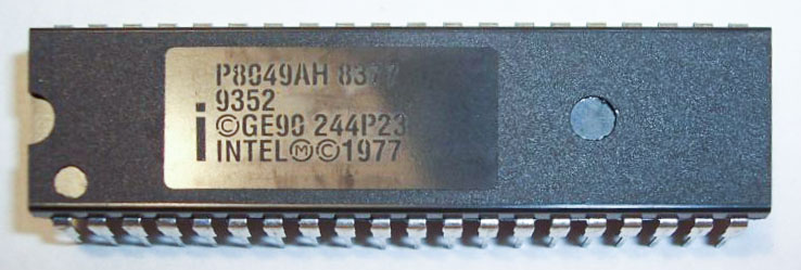
Intel_P8049_AH_controller
Original image from Deskthority Wiki. (Edited image is shown.)

The keyboard matrix itself did not amaze me, but instead the idea there was an entirely separate 8-bit microcontroller inside of the keyboard. Early keyboards may have used the P8049AH, which, there is still some stock available to purchase. I was fascinated with the idea an entire computer was necessary to run the keyboard, to use my “real” computer. Why did it take something as complicated as a microcontroller?

Abstract

After getting a couple of flashing lights working on a microprocessor, the next fun project is generally building some kind of Matrix.  At first I built a 5×5 LED matrix which was relatively simple to solder together.  When trying to make one much larger, the task because significantly more complex.  That’s when I decided to build a LED Matrix Shield for the Arduino which did not use Charliplexing, like the LoL shield.  I wanted something that was simpler to understand and (ultimately) code for.  Unfortunately, 5mm LEDs means 8 columns x 6 rows, instead of the traditional 8×8.

This is a quick video demonstrating the LED Matrix Shield for the Arduino.  This Matrix is an 8×6 “Normal” matrix.  (It is not Chairleplexed.)  Blue LEDs were used to give it a brilliant hue and to provide another source of light in dimly lit apartment homes.  Only one row of the Matrix is lit up at one time.  This is done to save power and because the ATMega processor of the Arduino cannot source or sink more than 200mA of current.

Update 10/6/2012:  Project page now available.

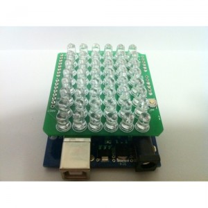
The scrolling message can be any string of characters between ASCII 32 and 255. The font is a 8×6 font based on 5×7 characters.  Click below to see a picture of the Shield sitting on top of an Arduino.

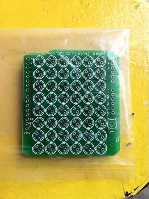
The PCB for my very first Arduino shield arrived today from BatchPCB. At first glance everything looks good. The silkscreen with my name and web address didn’t come out so well but that was probably my fault on trying to fit in too much.

Looking forward to assembling then with some Blue LEDs!