
Abstract
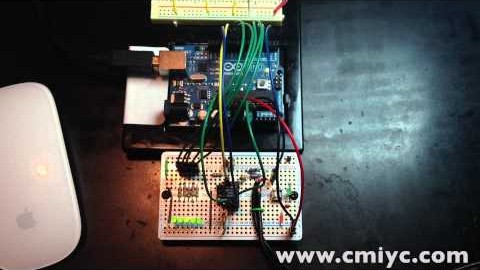
Mixed Signal Integration has a cool little chip that has 7 built-in bandpass filters. Run an audio signal through it and you have an instant audio spectrum analyzer! This is a simple spectrum analyzer based on an Arduino. Each of the 5 LEDs represent a single section of the chip’s 7 sections of audio spectrum.
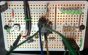
MSGEQ7 on Adafruit Protoboard
Electronics
If you want to replicate this setup, here is the hardware you’ll need to get.
Parts list:
- (1) - MSGEQ7 (Sparkfun)
- (5) - LEDs
- (5) - 470Ω Resistors
- (1) - 180kΩ Resistor
- (1) - 22kΩ Resistor
- (1) - 33pF Capacitor (Ceramic)
- (1) - 0.01µF Capacitor (Ceramic)
- (2) - 0.1µF Capacitors (Ceramic)
- (1) - Pushbutton
- (1) - Stripped Audio Cable
- Header Pins
- Jumper Wires
- Adafruit Perma-Prototype Board (or Breadboard)
Schematic:

MSGEQ7 Schematic
The application example from the MSGEQ7 Datasheet provides the circuit necessary. The 200k and 33pF are probably the most critical components. 200k is not a E24-value, so I used 180K. The 33pF shouldn’t be an issue to find. 470 ohms were picked to keep the amount of current flowing through the Arduino I/O pins low.
Firmware
Since there are only 5 LEDs, I decided to make each frequency band adjust the brightness via PWM. The more energy at each particular band will result in brighter LEDs. The code was compiled in Eclipse with Arduino-0023 Core on an Uno with an ATmega328.
Code is also available from Pastebin: MSGEQ7 Simple Spectrum Analyzer
#define msg7RESET 11
#define msg7Strobe 12
#define msg7DCout 0
const int LEDpins[7] = {3,5,5,6,9,9,10}; // there are 5 LEDs and 7 freq bands. So, repeat LEDs

#define pushButton 2

void setup() {
   // initialize the digital pin as an output.
   // Pin 13 has an LED connected on most Arduino boards:
   for (int x=0; x<7; x++) {
      pinMode(LEDpins[x], OUTPUT);
   }
   pinMode(msg7RESET, OUTPUT);
   pinMode(msg7Strobe, OUTPUT);

   pinMode(pushButton, INPUT); // never actually used in this example.
   digitalWrite(pushButton, HIGH); // Enable internal pull-up
}

void loop() {
   digitalWrite(msg7RESET, HIGH); // reset the MSGEQ7's counter
   delay(5);
   digitalWrite(msg7RESET, LOW);

   for (int x = 0; x < 7; x++){
      digitalWrite(msg7Strobe, LOW); // output each DC value for each freq band
      delayMicroseconds(35); // to allow the output to settle
      int spectrumRead = analogRead(msg7DCout);

      int PWMvalue = map(spectrumRead, 0, 1024, 0, 255); // scale analogRead's value to Write's 255 max
      if (PWMvalue < 50)
         PWMvalue = PWMvalue / 2; // bit of a noise filter, so the LEDs turn off at low levels

      analogWrite(LEDpins[x], PWMvalue);
      digitalWrite(msg7Strobe, HIGH);
   }
}
Demonstration
YouTube Video showing the light’s action along with some music. The music was created using GarageBand’s magic instruments. I liked the groove and how well the lights responded to it. Enjoy!
Project by AntiPuppet: