Category

Hardware Design

Category

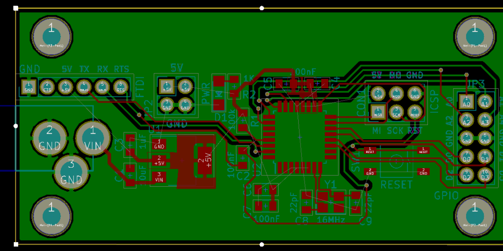
For an AddOhms series, I created a DIY Arduino I am calling the “Pyramiduino.” It is an ATmega328p based board in the shape of a triangle. Other than being cute, the shape does not offer any other benefit. The design features a 3.3 volt LDO Regulator, which is also the subject of this post.

I forgot a fundamental aspect of design: read the freaking datasheet. The board’s LDO regulator was not turning on. Adding a passive scope probe to the circuit suddenly fixed the problem. The regulator turned on. When touching the enable pin, it measured about 1.25 volts.  While I am sure Rohde & Schwarz would like me to ship scope probe with each board, that was not an option. With the impractical fix in place, I got to thinking about that voltage level. I remembered that the datasheet mentioned about 1.2 volts was needed for the “HIGH” threshold. Which meant, 1.25 volts applied to the pin enabled an active low input. Not only that, I remember the datasheet clearly said it had a pull-down resistor built-in. What was going on?

Continuing the DIY Arduino tutorial series, this AddOhms episode shows how to create a PCB in KiCad. I make a joke that the original design was a rectangle, which I found boring and pointless. So instead, I designed a triangle to give the board 3 points. Get it? Puns! I am calling it the Pryamiduino. To be honest, I found not having a constraint to be a problem. By forcing a specific board size and shape, many decisions were more manageable.

boring rectangular arduino nano clone
First design – Boring!

In the end, the video ended up more edited than I planned. KiCad is just so finicky and crashy that I could not make a coherent start to finish tutorial. At least, I could not work with a board at this level of complexity. Something simple like a 555 flasher would be easier to show from start to finish. I am planning some immediate follow-ups with quick tips on using KiCad. It is a frustrating suite of applications, but the results can be quite nice.

AddOhms Pyramiduino Show Notes

One of the last significant steps in a project is designing the custom PCB. This stage means creating a DIY Arduino board that is custom to the application. Two examples of my past projects are BinBoo, a Binary Clock, and Open Vapors, my reflow oven controller.

While working on a project for a friend, I got to thinking; it would be nice to have a checklist for circuit elements to include on a DIY Arduino board. In the early days, I forgot to add a filter cap to AREF, for example.

These tips are based on an 8-bit AVR design, like the ATmega328p chip. You could apply these tips to other 8-bit AVRs. Until now, I have not designed a custom board around a 32-Bit/ARM board. Though at only $16, I would be tempted to just solder the Teensy module directly to my finished board.

Below is a written list of items for a DIY Arduino checklist. If you’d like to see me design this board in KiCad, check out this AddOhms Tutorial.

As a kid, I got the book “Upgrading and Repairing PCs.” (Now in its 22nd edition.) It was the first book to explain to me the PC architecture. I considered, how were there so few pins on an AT-style keyboard connector when there were 101 keys on the keyboard? That is when I first learned about the keyboard matrix.

Intel_P8049_AH_controller
Original image from Deskthority Wiki. (Edited image is shown.)

The keyboard matrix itself did not amaze me, but instead the idea there was an entirely separate 8-bit microcontroller inside of the keyboard. Early keyboards may have used the P8049AH, which, there is still some stock available to purchase. I was fascinated with the idea an entire computer was necessary to run the keyboard, to use my “real” computer. Why did it take something as complicated as a microcontroller?

A couple of weeks ago I wrote about four current flow direction myths. As a follow up to that popular post, I decided to dedicate this month’s AddOhms electronics tutorial video to Current Flow. In episode #19, I tackle the question of which way does current flow.

You might have heard about “conventional flow” and “electron flow.” In conventional flow, we assume that current flows from the positive voltage towards the negative voltage. In digital, the “negative voltage” is usually called ground. However, that’s not how the electrons move nor is it how they carry the charge around a circuit path.

Electron flow is the description of how electrons carry a charge. Which is the negative voltage towards the positive? This confusion is a result of Ben Franklin mistakingly identifying how electrons moved so many years ago. Yet, we have kept the “positive” and “negative” labels as they are today.

The key though is that it doesn’t matter which method you use to analyze a circuit. Electrons move in a closed path. So whether they travel from positive to negative or from negative to positive, doesn’t matter!

AddOhms #19: Current Flow Direction

Check out the full AddOhms Electronics Video Tutorial on Which Way Does Current Flow on the AddOhms YouTube Channel.